We offer a 7 day replacement guarantee on all items that arrive defective or damaged. View our full policy here.


All payment methods are fully secure via SSL. We have the following payment methods available: Credit & Cheque Card; Instant EFT; QR Code Apps; Debit Card; MobiCred; and SCode.
Description
Structural Features:
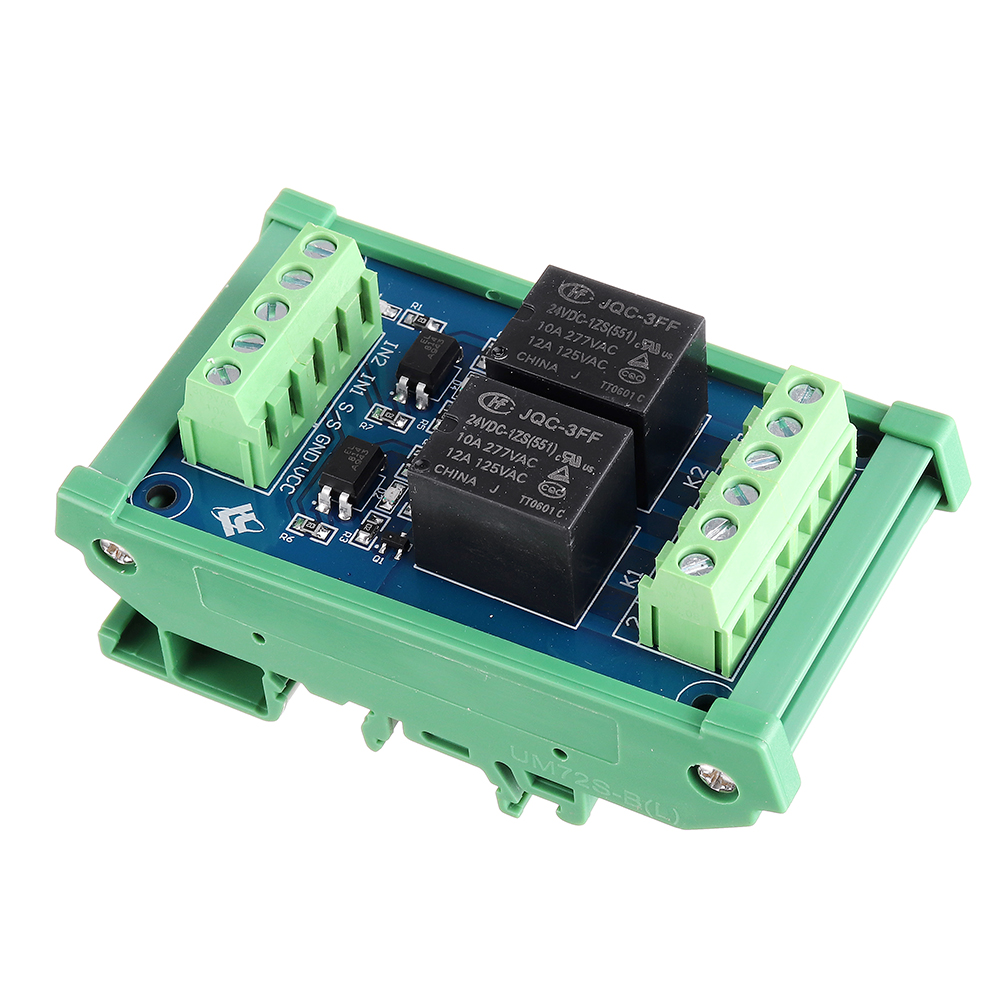
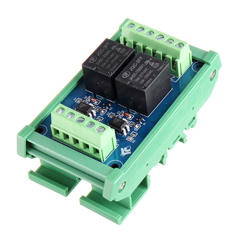
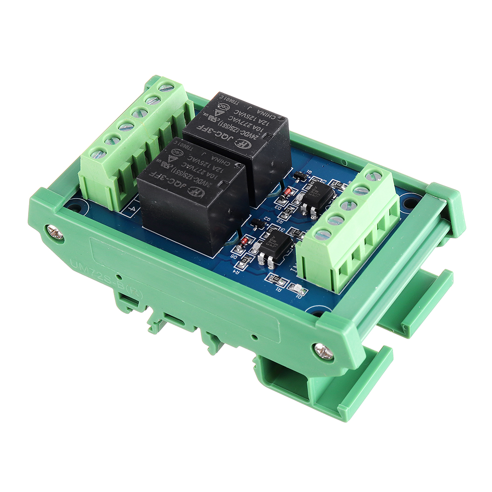
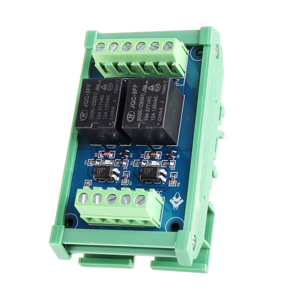
1. Use Hongfa relay, stable and reliable performance;
2. Compatible with two input modes of positive control and negative control;
3. Each channel has an LED action indicator for a more intuitive understanding of product performance;
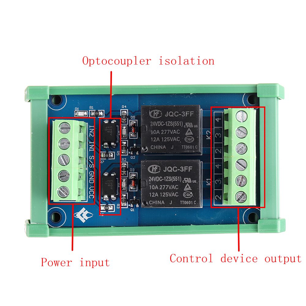
4. Each channel adopts optocoupler isolation to enhance anti-interference performance and isolation performance;
5. At the same time, the power supply and the "IN" control terminal are independently controlled;
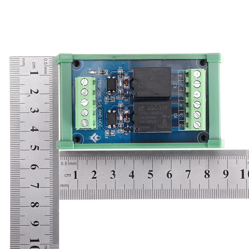
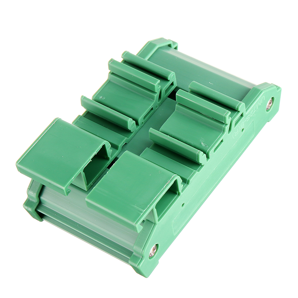
6. The module adopts the standard "DIN" rail-type installation design, which is convenient and quick to install, firm and stable.
Technical Parameters:
1. Trigger signal: DC5V / 12 / 24V (Optional)
2. Each trigger signal current: 5mA
3. Power supply voltage: DC5V / 12 / 24V
4. Each coil current: 18.8mA
5. Contact type: one normally open and one normally closed (single pole)
6. Maximum load current of each contact: 10A
7. Action time: below 12ms
8. Reset time: less than 4ms
9. Maximum switching frequency: 18000 times / hour
10. Mechanical life: more than 20 million times
11. Relay installation: plug-in type (No)
12: Module installation method: DIN standard rail installation
Positive control wiring introduction:
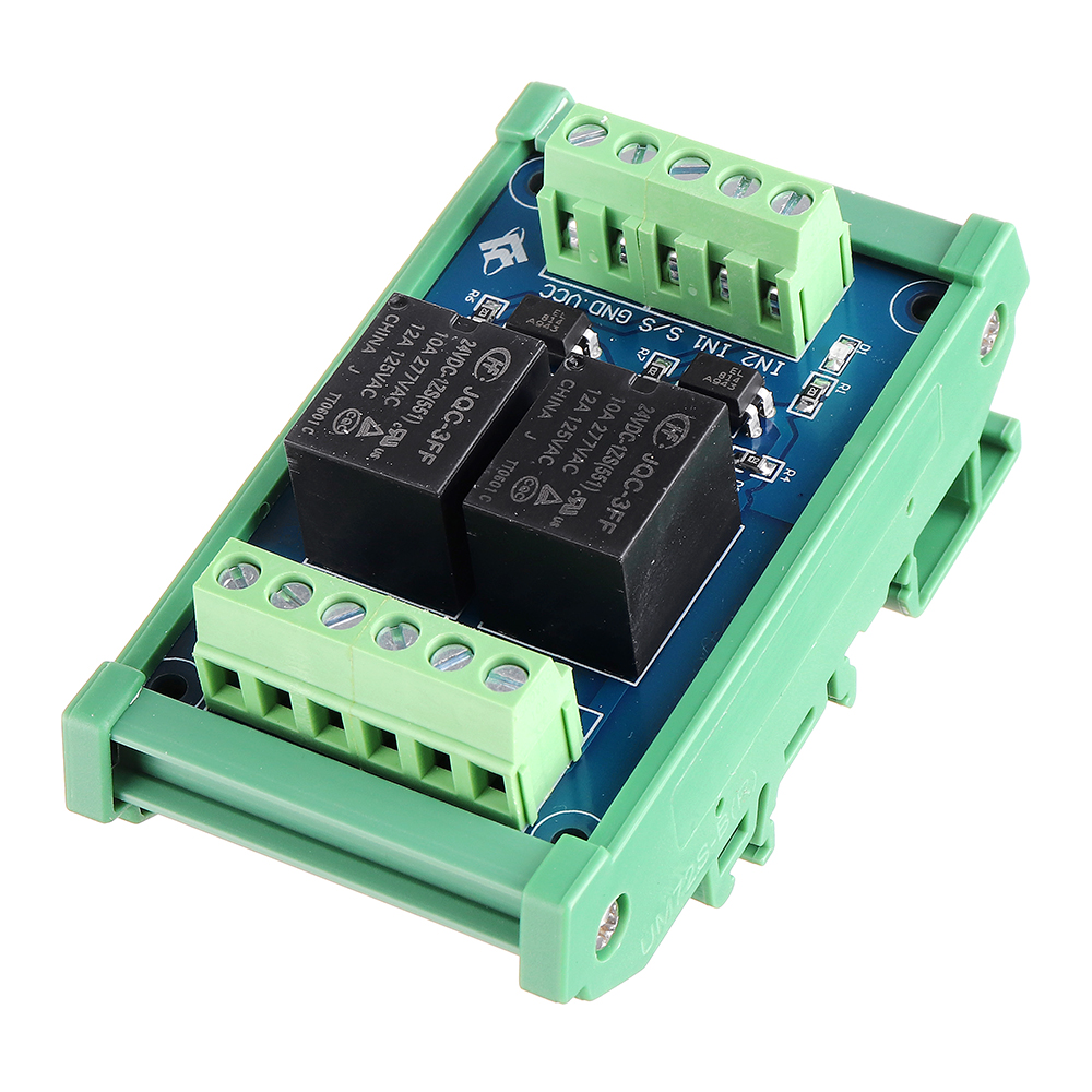
1. Power input terminal:
VCC is connected to the positive voltage, GND is connected to the negative voltage, and S / S is connected to the negative voltage
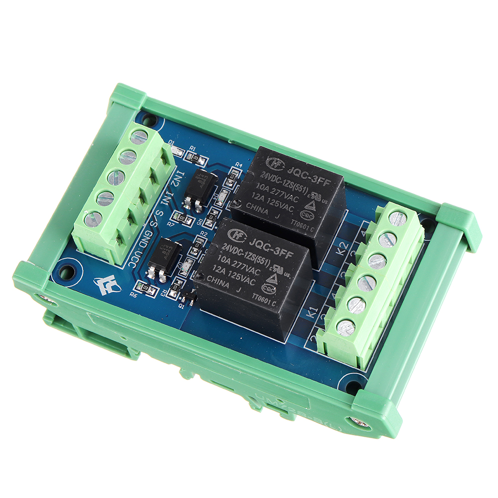
IN1, IN2 are connected to positive voltage control, IN1 controls KI terminal, IN2 controls K2 terminal
2. Control device output:
The output terminal is clearly marked with 234, 3 is a common point, 2 is normally open, and 4 is normally closed. K1, K2 means two relays work.
Negative control wiring introduction:
1. Power input terminal:
VCC is connected to the positive voltage, GND is connected to the negative voltage, and S / S is connected to the positive voltage
IN1, IN2 are connected to negative voltage control, IN1 controls KI terminal, IN2 controls K2 terminal
2. Control device output:
The output terminal is clearly marked with 234, 3 is a common point, 2 is normally open, and 4 is normally closed. KI, K2 means two relays work.
Package includes:
1 x Relay board
Package includes:
1 x Relay board